STANDARDIZATIONS
There are two main organizations whose standards are used for creating engineering drawings with GD & T.
ASME Y14.5 is a complete definition of GD & T which consists of all the symbols, their meaning, rules of using them, and principles. Also, it has details on verification of manufactured parts by inspection of dimensional measurements, gaging or measuring devices or machines, but it is only for defining acceptable parts and not for measuring. It is followed in all of America and also referred by other countries.
Most of the European countries follow ISO standards for creating engineering drawings. The definitions are comprised of the standard ISO/TC213.
Although both standards are used for GD & T, there are several differences, but the meaning for the symbols remains the same.
Datum is the perfect point, line, or plane from which other dimensions and features can be measured. DRF is a 3-dimensional cartesian co-ordinate which is made by three datum planes. Any part without constraints has 3 degrees of freedoms (DOF) in translational direction and 3 DOFs in the rotational direction. DRF restricts all the DOFs so that a part can manufactured and measured. Three datums are classified as primary datum, secondary datum, and tertiary datum. Datums are generally designated in alphabetical order from A to Z with exception of letters I, O & Q. If alpha series is all used double alpha series (AA, BB, CC, …, ZZ) can be used. Datum is shown as figure no.1.
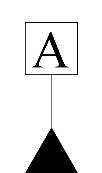
Figure 1: The above figure shows datum symbol
The datum features are selected according to the functional requirement of the part. Generally, functional surfaces, mating surfaces, readily accessible surfaces & the surfaces which can be used to take repeated measurements should be selected as the datum.
The dimensions are generally specified according to the assembly requirement with tolerances.
Feature control frame is the main component of GD & T. It states the instructions regarding the features that need to be controlled. It is used to control form, orientation, location, and runout. The table of symbols shows the application of symbols. Along with these, material modifier conditions can also be specified in FCF. The FCF looks as given below:
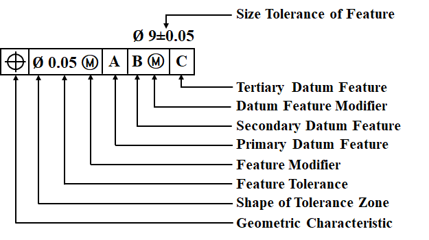
Figure 2: The above figure shows Feature Control Frame
A geometric characteristic symbol is given in the first section of FCF. There is a total of fourteen symbols which are further classified into five categories. Table no. describes these symbols.
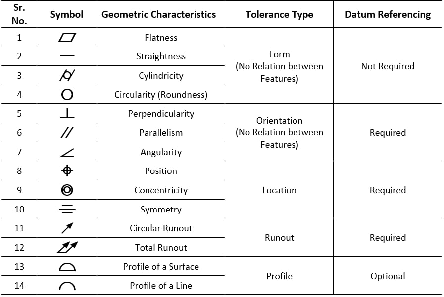
Let's understand each of them individually.
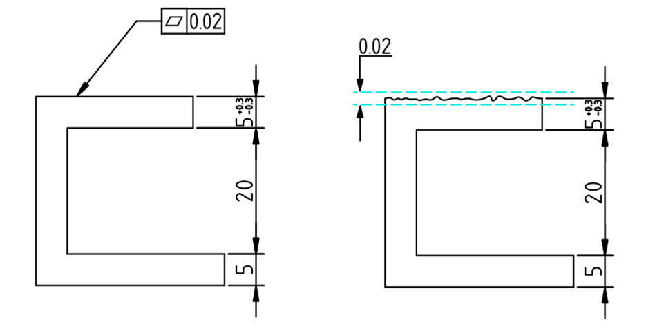
Figure 3: Flatness tolerance with 0.02 mm range ensuring the surface is within those limits
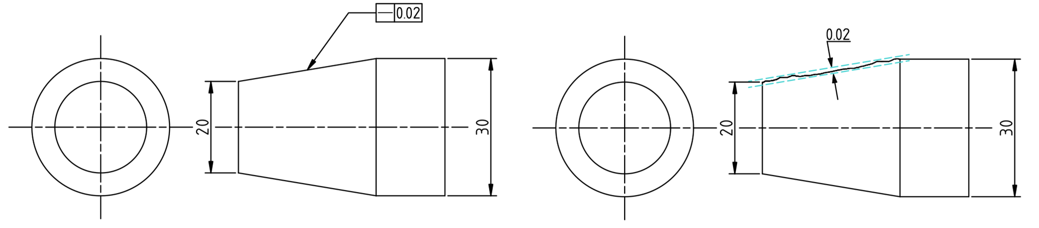
Figure 4: Straightness tolerance with 0.02 mm range ensuring the line edge is within those limits.
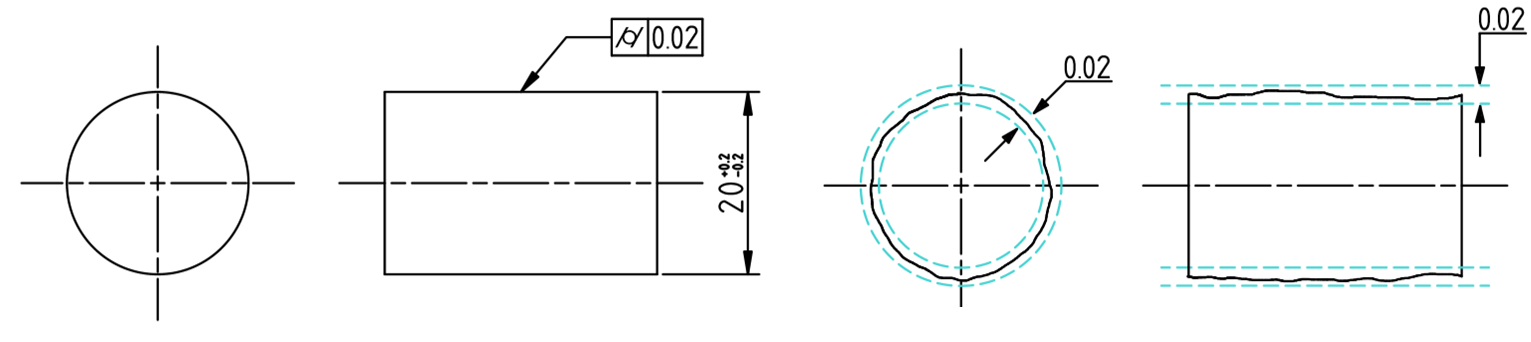
Figure 5: Cylindrical tolerance with 0.02 mm range ensuring the surface is within those limits.
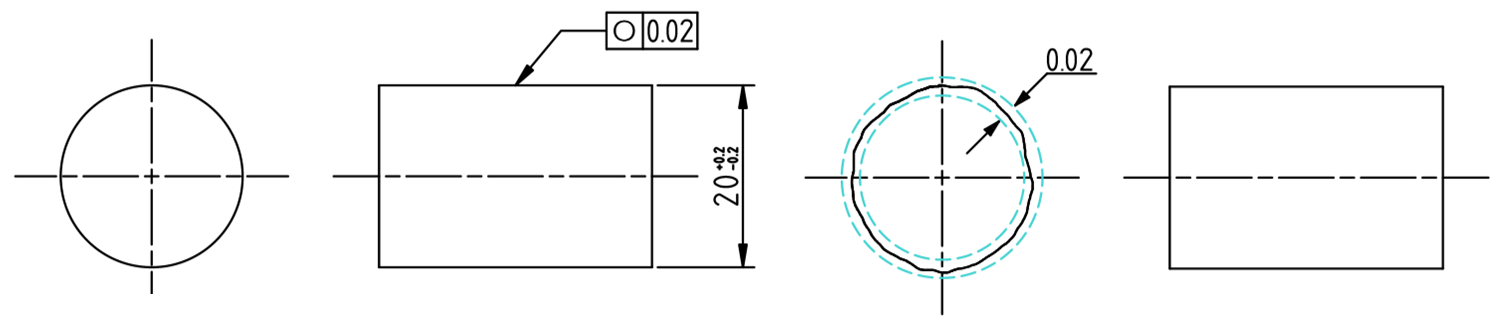
Figure 6: Cylindrical tolerance with 0.02 mm range ensuring the surface is within those limits
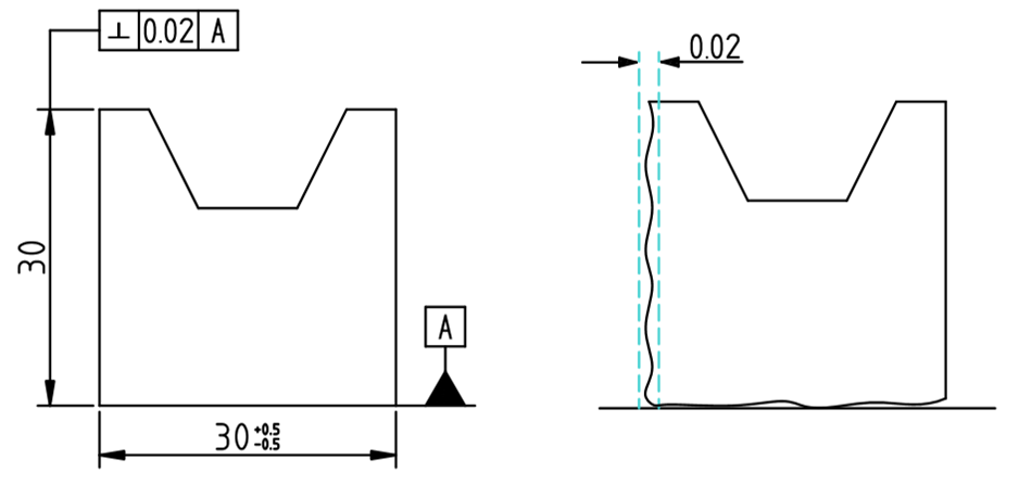
Figure 7: Perpendicularity tolerance with Datum A having 0.02 mm range ensuring the surface is within those limits
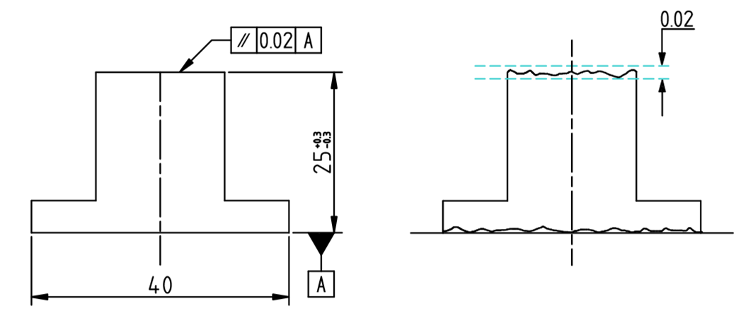
Figure 8: Parallel surface tolerance with Datum A having 0.02 mm range ensuring the surface is within those limits
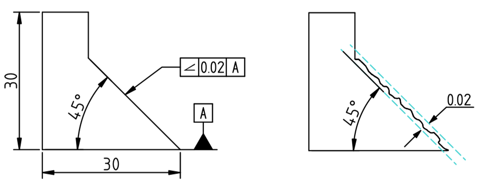
Figure 9: Angularity tolerance with Datum A having 0.02 mm range ensuring the surface is within those limits
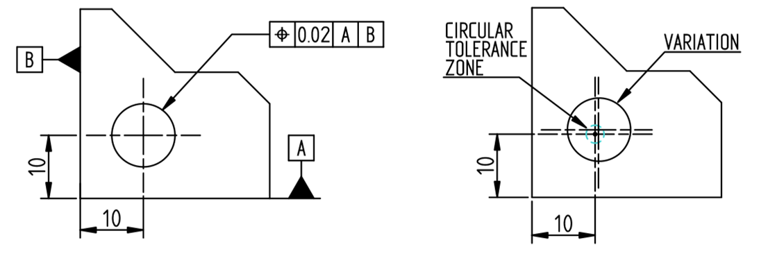
Figure 10: Position tolerance with Datum A & B having 0.02 mm range ensuring that the axis is within the circular tolerance zone of 0.02
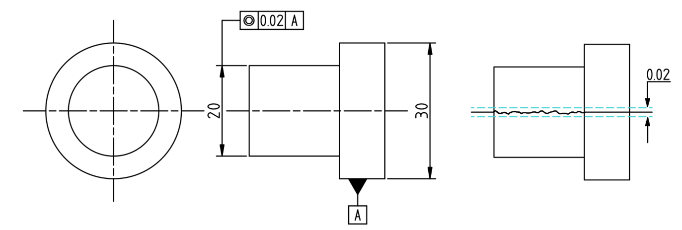
Figure 11: Concentricity tolerance with Datum A having 0.02 mm range ensuring the Axis is within those limits
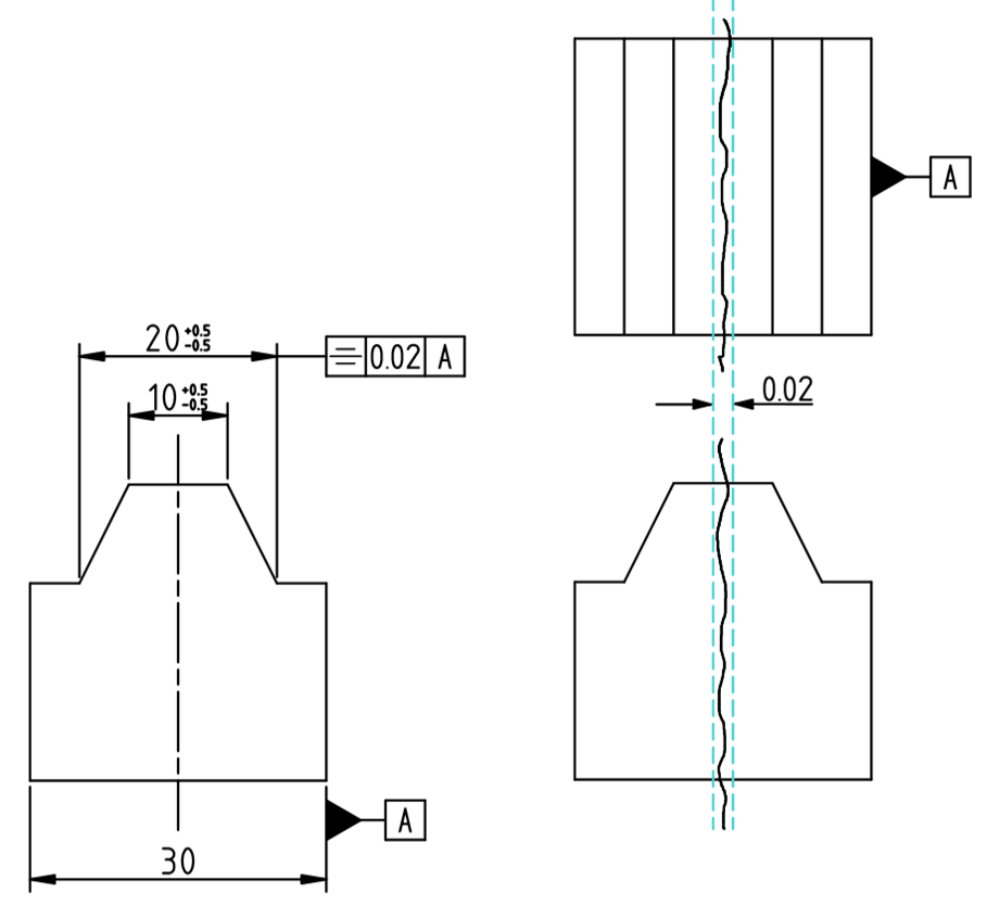
Figure 12: Symmetry tolerance with Datum A having 0.02 mm range ensuring the midplane is within those limits
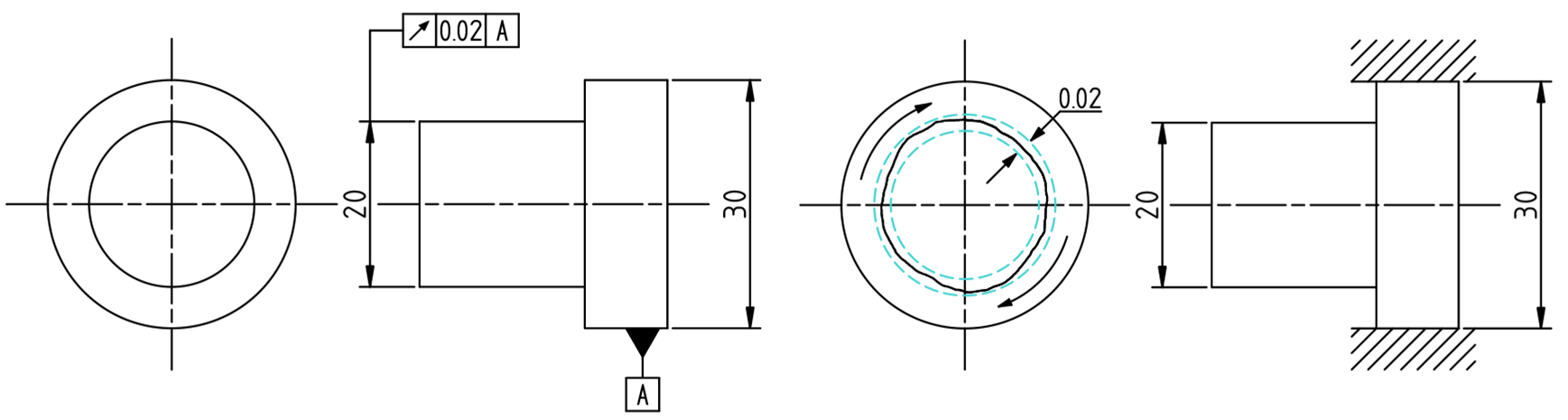
Figure 13: Circular runout tolerance with Datum A having 0.02 mm range ensuring the circle is within those limits
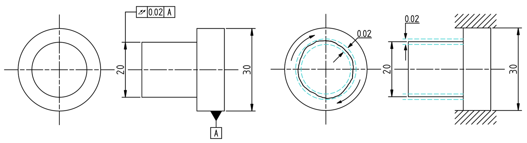
Figure 14: Total runout tolerance with Datum A having 0.02 mm range ensuring the surface is within those limits
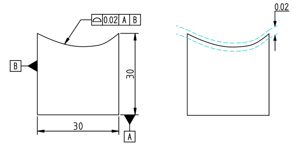
Figure 15: Profile of a surface tolerance ensuring the surface is within 0.02 mm tolerance from Datum A and B
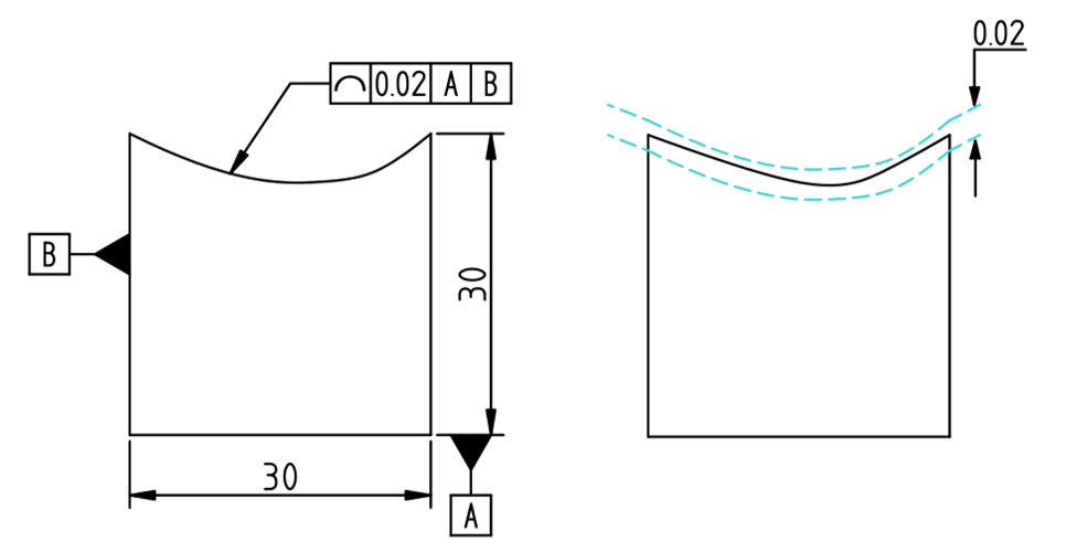
Figure 16: Profile of a line tolerance ensure the line on the surface is within 0.02 mm tolerance from Datum A and B
Only one symbol can be specified in one FCF. If there is a need for two or more symbols, then extra FCF should be added.
The second section of FCF gives information regarding tolerance value, shape of tolerance and material modifier condition of that feature. Ø symbol specifies a circular tolerance zone otherwise it is taken as two parallel planes or wide tolerance zone according to the geometric characteristic symbol. The value indicates the allowable deviation from the basic feature. The material modifier conditions are two types: Maximum Material Condition (MMC) & Least Material Condition (LMC). They are useful because they can add bonus tolerance to the feature. If it is not specified then the condition is known as Regardless of Feature Size (RFS) and the tolerance remains same for a feature.
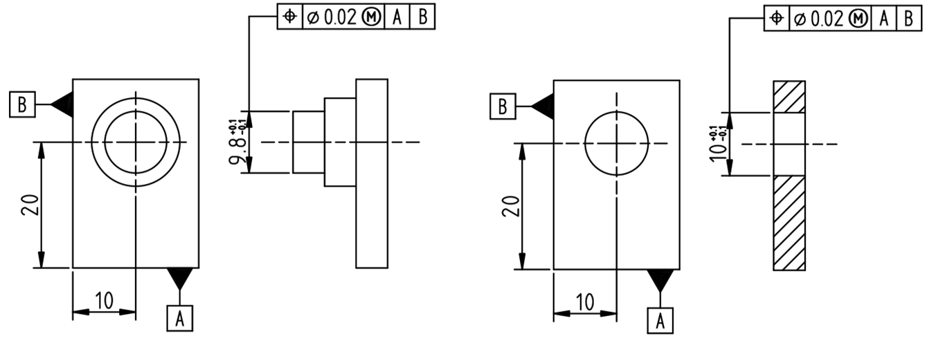
Figure 17: An MMC call out indicates that as the part dimension approaches near MMC the tolerance becomes tighter.
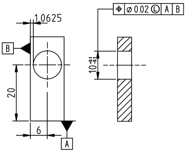
Figure 18: An LMC call out indicates that as the part dimension approaches near LMC the tolerance becomes tighter.
From the third section onwards, datum features are specified. The third section specifies the primary datum feature, fourth section specifies secondary datum feature & the fifth section specifies tertiary datum feature. Datum features can also be given material modifiers and these are known as Maximum Material Boundary (MMB), Least Material Boundary (LMB). The default is Regardless of Material Boundary (RMB) if not specified. Although the datums are designated in alphabetical order, the order of datum in FCF decides the precedence of one datum over others. Also, it is not always necessary to define all the datums in FCF. If the geometric characteristic can be defined using only one datum then only one datum is enough.
PLATFORMS
Although the implementation of GD & T solely depends on experience, knowledge, and understanding of designer, there are tools available to help in the use of GD & T. These tools not only shows the callouts and annotations in computer-aided drafting, but they also give guidance on GD & T.
If you have already read about our previous blog on tolerance analysis, you probably know CETOL 6σ, GD & T Advisor software by Sigmetrix. It is a plug-in for Creo and works in Creo's native environment using the symbols which are already in Creo. It has both ASME & ISO standards and is available in English, German, and Simplified Chinese Languages.
It works as a guide while the designer is applying GD & T. It shows which form, feature, and feature control are suitable for selected face, edge, or feature. It has a dialogue box that shows which features are fully defined and which needs more input. The help section consists an interactive design for understanding the symbols and their meanings.
DimXpert is an automatic dimensioning tool in SolidWorks. It gives dimension to the 3D model automatically. While dimensioning, it has an option of including tolerances. 3 settings define the Auto Dimensioning Scheme. These are:
- Part Type: This setting has two options, Prismatic for block geometry and Turned for Cylindrical Geometries.
- Tolerance Type: In this step, you have to define which type of tolerance system is going to be used. The options are conventional ±tolerance and Geometric tolerance.
- Pattern Dimensioning: It lets you give linear or polar dimensioning system for patterns.
The dimensions created by DimXpert can be modified or edited according to need. The best thing is that the dimensions can be readily exported to eDrawings or extracted to 2D Drafting in SolidWorks.
The DimXpert is a powerful tool to implement GD & T but it should be validated by the designer to make sure it's accurate. Also, the assigning is done by the software so the position of FCF might not be as you required in the 2D drawing. In that case, the position of FCF has to be modified in the CAD model to make it suitable for 2D drafting.
ADVANTAGES
- It communicates the way the designer wants the part to be manufacture.
- It saves money by avoiding rework and scrape.
- It helps in maintaining interchangeability of parts in assembly.
- The tolerances can be loosened up with a circular tolerance zone as opposed to a traditional square tolerance zone.
- It helps quality control & inspection by defining the DRF to work as a base for measurements.
- As long as the employees are trained, the drawing will be interpreted in the same way by all the departments so it ensures accurate communication.
LIMITATIONS
- The standards are pretty lengthy and require time to memorize for effective use.
- The implementation depends on the knowledge and expertise of users. So, everyone that is going to use GD & T such as Designer, Manufacturer, and Quality Control has to be trained to interpret the GD & T.
- There are 2 standards so cross standard collaboration will require expertise in both standards.
IMPROVIANS TAKE
Hopefully, this blog gave you meaningful insights on GD&T. As discussed, smart and effective use of it can help you save a ton of time during manufacturing and inspection thus improving productivity and reducing cost. If you are a first-time user, it is advisable to get your drawing reviewed from someone more experienced or an external consultant. At Improvians, we can help you with all your GD&T requirements.


